
Home » Precast Connector Resources »
Hydrogen sulfide gas turns to acid on the crown of a sewer manhole and eats the concrete. DURA-PLATE 100 puts a PVC liner between the gas and the concrete, cast in at the plant so it is part of the structure from day one.
The objective of this specification is to cover the supply and installation of a vacuum formed semi-rigid liner for use in wastewater and light industrial concrete structures to effectively shield the interior of the structure from corrosion.
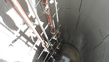
1. What the liner is
Liner shall be Dura Plate 100 as supplied by A-LOK Products, Incorporated, Tullytown, Pennsylvania.
The liner, channel joints, H-joints and corner joints shall be manufactured from an Acrylic PVC Alloy. All sheet compound will result in a semi-rigid material suitable for thermoforming to the contour of the structure and shall maintain a nominal wall thickness greater than 0.065 inches.
The fabricated liner panels shall be joined together by a slotted strip of EPDM rubber according to the manufacturer’s specification as illustrated in Figure 1A.
Sections of lined concrete structures shall be joined together by an approved butyl strip (A-LOK Products, Inc. Tullytown, PA. MT-329) designed to produce sufficient squeeze-out between PVC returns.
The liner shall be light in color to reflect light.
2. How it anchors to the concrete
The design of the liner system shall insure that it will conform to the contour of the structure and form a permanent mechanical bond to the concrete through use of preformed horizontal ribs and dovetails. The liner will be formed in such a manner that the joints between the structure sections will be afforded protection through the use of a continuous return into the joint for a minimum of .50 of an inch.
A combination of standing ribs and mechanical dovetails shall be used to secure the liner panels to the wall of the structure and shall be spaced a maximum of 6.0 inches apart.
Liner with locking extensions shall be able to withstand a test pull of 100 pounds per linear inch applied perpendicular to the concrete surface for a period of 60 seconds. No rupture of the locking extensions or withdrawal from embedment shall be acceptable.
All panels shall be vacuum tested for pinholes by the liner manufacturer during the molding process to withstand a minimum of 25 inches of mercury for a period of 60 seconds.
3. What it stands up to
The liner is tested against the chemicals a sewer actually carries.
| Chemical | Solution |
|---|---|
| Sulfuric Acid (H2SO4) | 20% |
| Sodium Hydroxide (NaOH) | 5% |
| Ammonium Hydroxide (NH3OH) | 5% |
| Nitric Acid (HNO3) | 1% |
| Ferric Chloride (FeC13) | 1% |
| Soap | 0.10% |
| Detergent | 0.10% |
| Test | ASTM Method | Minimum Value |
|---|---|---|
| Tensile | D-638 | 6,100 psi |
| Elongation | D-638 | 28.5% |
| Tensile Modulus | D-638 | 325,000 psi |
| Flexural Strength | D-790 | 9,200 psi |
| Flexural Modulus | D-790 | 340,000 psi |
| Tensile Impact | D-1822 | 640 in-lb |
| Gardner Drop Dart | D-5420 | 90 ft-lb/in2 |
Dura Plate 100 Liner shall be made from Acrylic PVC Alloy sheets that resist bacteriological and fungal development. Sheet shall not readily provide a source of nutrients for bacteria and fungi.
Conclusion of Fungus Resistance Testing: The sheet samples did not allow any fungus growth (rating of 0). Conclusion of Bacteria Resistance Testing: The sheet samples did not allow any bacterial growth (rating of 0).
The epoxy mortar used at pipe openings was put through a 12-year soak in 20 percent sulfuric acid by an independent laboratory. The results show no discernable change in either sample because of the acid soak.
4. Casting it in at the plant
The liner goes into the form before the pour. A-LOK’s precast installation guidelines, in order.
Material should be kept in a dry secure location and moved into production as needed.
Riser and Base Components shall be assembled in accordance with Figure 1A of the standard specification. Form required as a fixture. A level area will be required for assembly. Fasteners shall be placed on 3″ centers.
The liner panels when assembled shall form a circular cylinder that fits snugly against the inner steel core of the form. A removable extruded rubber profile or suitable one-sided tape can be used to seal the liner against the core to prevent concrete fines from washing down between the liner and steel core.
When pouring base sections shorter than core height, duct tape and seal liner to core to prevent excessive bleeding between liner and core.
Openings for pipe penetrations should be jigsaw cut prior to casting. Use hole former as template for opening.
Concrete poured around the liner shall be distributed evenly to prevent shifting of the liner. Concrete poured against the liner shall be vibrated or compacted in a manner to protect the liner and produce a dense homogenous concrete to securely anchor the assembly to the exposed surfaces on the interior of the structure. Self-consolidating concrete does not require vibration.
Preferred lifting provisions shall be of a non-penetrating type (i.e. swift lift). If penetrating lift provisions are used, they must be filled and properly sealed after contractor installation as not to provide a point of infiltration.
Curing of lined sections shall be done without steam and no direct heat should be applied to the core surface of the form. If you have an application that will see continuous high temperatures, bring this up with your A-LOK representative for project specific information and instruction.
When extracting the steel core, care should be taken to protect the liner from damage. Instruments with sharp or jagged edges should not be used to release the forms from the liner.
Visual inspection of the liner shall be made after demolding and any cuts or tears shall be repaired by following the manufacturer’s repair recommendations.
Care shall be taken to yard all material in a manner to protect liner from coming in direct contact with the ground, or submerging liner in prolonged ice. Lined sections should never be placed on surface that would puncture the liner. Highly recommend placing sections on dunnage.
When shipping Dura Plate lined structure components, care should be taken to protect liner from chains and binders. Do not allow lined structures to sit unprotected outdoors in wet or freezing temperatures for extended periods of time.
5. Setting lined sections in the field
The horizontal joints between sections of lined concrete structures can be made by either butyl or a combination of butyl and rubber joint per the recommendation of the concrete manufacturer.
Joint surfaces must be clean to ensure proper adhesion of the butyl. An application of a butyl based primer will produce the highest degree of adhesion to the joint surfaces.
Place specified butyl material as indicated in Figures 2A and 3A. Butt ends of material together. Material should never be overlapped. Butyl material shall be an approved strip per Section 2.4.
Butyl shall be of proper size as dictated by annular space.
Lined sections should be carefully centered and lowered to complete coupling process. Apply sufficient pressure to properly seat joint and achieve squeeze out.
After structure is in place, care should be taken to properly plug all lift pin inserts or holes with a suitable non-shrink grout.
The installing contractor shall take all necessary measures to prevent damage to the liner due to material handling, installation, or equipment or material used in installing, or used in or taken through the structure.
6. Steps, pipe openings and the frame
Steps shall be attached by either casting a preformed polypropylene insert to accept a polypropylene drive in step (Fig. 4), or by casting or drilling a precise hole to accept a polypropylene press fit step (Fig. 4A), as per the recommendations of the step manufacturer.
After installation of either the steps or ladders, the junction point of the device and the liner shall be sealed by applying an approved butyl caulking material (A-LOK Products, Inc., Tullytown, Pennsylvania, Lap Sealant).
Pipe penetrations through the lined wall shall be afforded protection by applying .125 inch trowelable, chemical and corrosion resistant epoxy mortar to the unlined exposed areas within the openings and shall overlap the liner wall a minimum of 1.50 inches as illustrated in Figure 5A.
Corrosion protection between the lined concrete structure and the cast iron frame and cover shall be obtained through the use of a telescoping Liner System (A-LOK Products, Inc., Tullytown, Pennsylvania, Water-LOK Connector) illustrated in Figure 6A below.
Corrosion protection shall be afforded for aluminum entry frames and doors by fabricating a semi-rigid riser to match the inside dimensions of the access frame.
7. Testing
In-plant inspections of panels cast into concrete sections shall be visually inspected for cuts or tears and shall be repaired following the manufacturers recommendations.
When required, the following ASTM standard should be followed for vacuum testing of a circular manhole structure: ASTM C-1244 latest version “Standard Test Method for Concrete Sewer Manholes by the Negative Air Pressure (Vacuum) Test Prior to Backfill”.
If vacuum testing of installed structure is required, liner shall be properly supported as not to put excessive force on liner. It would be recommended to have an A-LOK representative assist contractor on initial test as to instruct on proper procedures of supporting liner.
The latest version of the ASTM C-1958 “Standard Guide for Soil-Tight Grouted Connections Between Concrete Pipe and Concrete Structures” provides guidance for opening sizing and grouting procedures for precast concrete pipe connections to precast structures.
An internal standpipe can also be used to measure ground water to determine hydrostatic pressure and adjust vacuum.
8. Flat wall structures
The same liner comes in a flat wall version for box structures, tanks and vaults.
Liner panels with horizontal and/or vertical dovetails in custom sizes up to a 50″ (W) x 90″ (H) panel.
When required, one of the following ASTM standards should be followed for vacuum testing of a box structure: ASTM C-1719 “Standard Test Method for Installed Precast Concrete Tanks and Accessories by the Negative Air Pressure (Vacuum) Test Prior to Backfill”; ASTM C-1227 “Standard Specification for Precast Concrete Septic Tanks”; ASTM C-1613 “Standard Specification for Precast Concrete Gravity Grease Interceptor Tanks”.
9. Specification language for your drawings
Engineers can lift this list straight into a spec. It is Part 10 of the DURA-PLATE 100 specification, as written.
- (1) The concrete structure shall have a liner that is integrally cast with the precast section, at the time of manufacture.
- (2) The liner shall be manufactured from an acrylic modified PVC alloy.
- (3) The liner shall be thermo-vacuum formed to create a semi-rigid liner.
- (4) The liner shall conform to the interior diameter of the structure.
- (5) The liner shall be formed with dovetail ribs so that it is securely anchored to the concrete structure.
- (6) The liner shall be formed with returns into the bell and spigot joints to allow for butyl sealant to be placed and to eliminate the need for any field welding of the joint.
- (7) The liner shall be light in color to reflect light.
- (8) The liner shall have both antifungal and antibacterial properties that will not readily provide a source of nutrients for bacteria or fungi.
- (9) The liner shall maintain a nominal wall thickness of 0.065″ thick.
- (10) The liner panels shall be joined together by an EPDM slotted rubber strip.
- (11) All materials shall meet the physical and chemical properties specified in the appropriate ASTM specification.
- (12) The liner shall be Dura Plate 100 as supplied by A-LOK Products, Incorporated. Tullytown, PA, or approved equal.
Download the full DURA-PLATE 100 specification and the installation guidelines, also linked from the DURA-PLATE 100 product page.
Frequently asked questions
What is DURA-PLATE 100 made of?
The liner, channel joints, H-joints and corner joints shall be manufactured from an Acrylic PVC Alloy. All sheet compound will result in a semi-rigid material suitable for thermoforming to the contour of the structure and shall maintain a nominal wall thickness greater than 0.065 inches.
How does the liner stay attached to the concrete?
The design of the liner system shall insure that it will conform to the contour of the structure and form a permanent mechanical bond to the concrete through use of preformed horizontal ribs and dovetails. A combination of standing ribs and mechanical dovetails shall be used to secure the liner panels to the wall of the structure and shall be spaced a maximum of 6.0 inches apart.
Can lined sections be steam cured?
Curing of lined sections shall be done without steam.
How are pipe openings protected in a lined manhole?
Pipe penetrations through the lined wall shall be afforded protection by applying .125 inch trowelable, chemical and corrosion resistant epoxy mortar to the unlined exposed areas within the openings and shall overlap the liner wall a minimum of 1.50 inches as illustrated in Figure 5A.
Is there a flat wall version?
Liner panels with horizontal and/or vertical dovetails in custom sizes up to a 50″ (W) x 90″ (H) panel.
Lining a structure for a corrosive service?
Tell us the structure, the diameter and the joint type and we will size the liner.